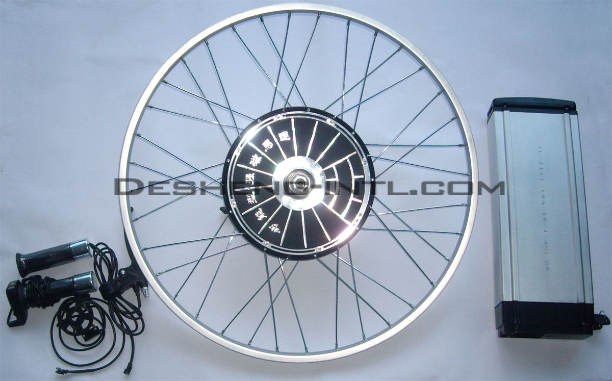
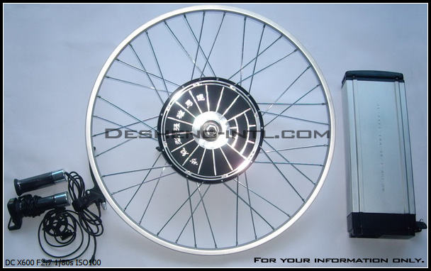
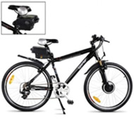
Front Wheel E-Bike Conversion Kit
|
| |
1× Motor Wheel(mounted with rim 20”-28” and spokes)
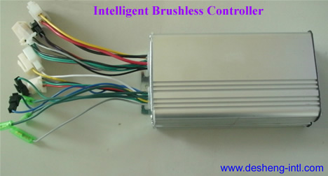
1× Intelligent Brushless Controller
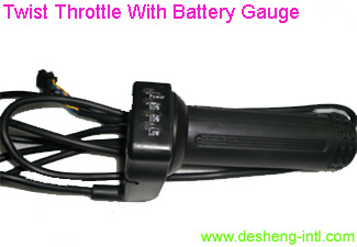
1× Twist Throttle With Battery Gauge
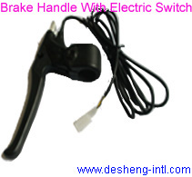
1× Brake Handle With Electric Switch
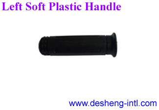
1× Left Soft Plastic Handle
1× Battery Pack : SLA,Ni-MH,Li-Poly Battery Available
1× Intelligent Three -Stage Charger
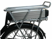
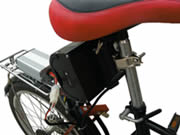
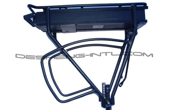
1× Battery Rack
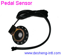
1× Pedal Sensor
1× Battery Bag |
|
|
Main Information of The E-Bike Conversion Kit
Type: Front wheel kit.
Autonomy: 24 to 50 km kits with brushless motor.
(autonomy is more if you pedal).
Speed: 25 km/h (For EU),0-32Kpm(for US),. Faster than a car into the traffic jam!
Battery life: 300 cycles.
Operation temperature: 4 to 38 °C (40 to 100 °F)
Weight: 17 to 24 kgs (36 to 52 pounds)
Charge time: within 8hours
Different power Brushless motor for different customer(24-48V,200W-600W available)
Batteries: different battery pack(voltage system) for different motor,SLA,Ni-MH,Lion-poly battery pack available
Charger: 110/220 Volts three stage intelligent battery charger
Could be easily installedl on 99,9 % of bicycle.
Available in 20, 24,26,28 inches sizes.
|
Motorized Wheels |
|
|
|
Dimension Drawing(PDF) Motor Performance Curve (PDF) |
Dimension Drawing(PDF) Motor Performance Curve (PDF) |
Features:
High Power Efficiency, H igh torque, robust in over-load, high reliability, long lifetime.
the main specification of the motor are shown in the below table:
|
| |
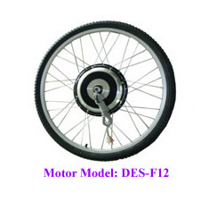
Motor Model:
Specifications: |
DES-F12
Front Hub Motor
Brushless/Geareless |
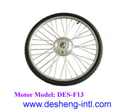
DES-F13
Front Hub Motor
Brushless/Geared |
Outer Diameter (mm) |
239 |
143 |
Hub Width(mm) |
82 |
90 |
Power Range(W) |
200W ~7 00W |
250W |
Voltage Range(VDC) |
24V/36V /48V |
24V/36V |
Speed(R/Min) |
175 ~ 300 |
175 ~ 300 |
Efficiency (%) |
85% |
85% |
Weight(Kg) |
5 KG |
3 KG |
|
|
|
|
|
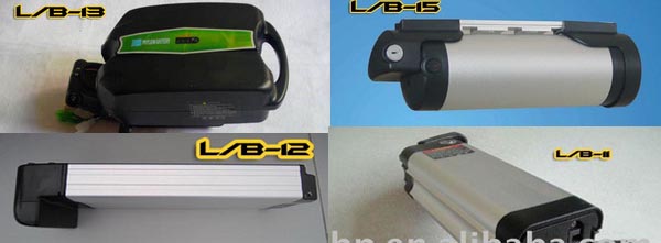
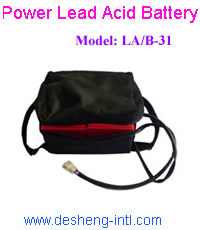
Battery Packs For E-Bike |
|
|
|
|
|
|
|
|
Model |
Dimensions
(L*W*H) |
Capacity |
Weight(kg/pc) |
Charger-Discharge
Curve |
L/B-11 |
3 7 0*85*8 5 mm |
24/36/48V10AH |
2.6/3.5/4.5kg |
L/B-11 |
L/B-12 |
330*145* 60 mm |
24/36V10AH |
2.6/3.2kg |
L/B-12 |
L/B-13 |
300*145*145mm |
24V10AH |
3 kg |
L/B-13 |
L/B-14 |
180*120*95mm |
24 /36 V10AH |
2.5/3kg |
L/B-14 |
NM/B-21 |
350*110*55mm |
24/36/48V10AH |
3 /3.5/4.5 kg |
NM/B-21 |
LA/B-31 |
15 0 *98*94mm |
12V12AH |
3.8kg |
LA/B-31 |
| |
(Remark: The dimensions in the table are based on the sizes of 36V10AH battery packs.) |
|
|
|
|
|
|
|
|
|
|
|
|
Intelligent Brushless Controller |
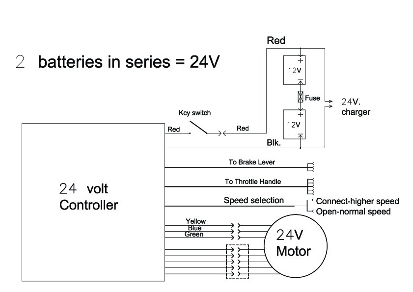
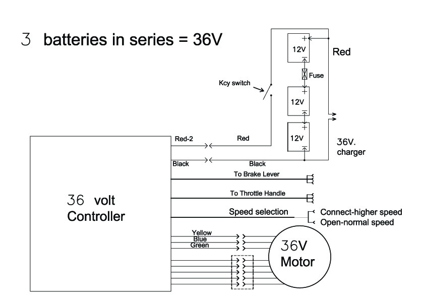
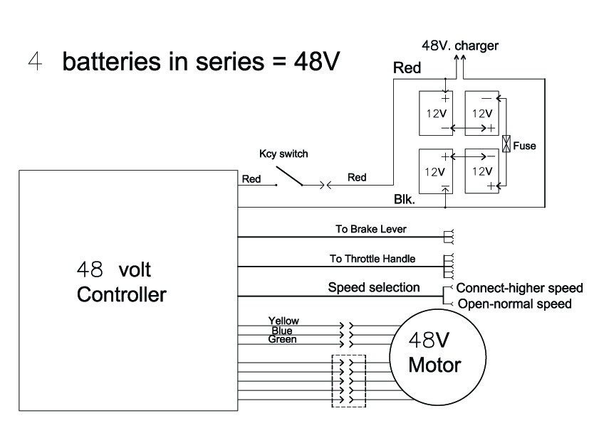
click here to see the wiring diagram
Features:
Overcurrent and low-voltage protection, immediate and pedal first start available,
cruise control, regenerative braking , EABS system.
Voltage:24V/36V/48V Current:20A
|
| Controller Model: |
Pedal First Controller: The Motor starts when speed reaches 5-7km/hr
Advantage of pedal first controller:
Motor starts after reaching 5km/hr to 7km/hr and this is a very good design for the following reasons.
1) It does not put a sudden over load on the battery which is good, if the circuit is connected to fuse it will not blow the
fuse as the starting current peak is lower.
2) For safety reasons - If the rider on the bicycle accidentally twists the throttle, this action would cause sudden
movement with the 0km/h system.
3) More Power: This controller with permit higher current and torque than the 0km/hr system.
|
0KM-Controller: The Motor will start immediately. ( 0km/hr Start )
Advantage of the 0km/hr system
1) It work more efficiently while starting.
2) It is more fun to ride an e-bike that starts from a stopped position. You will feel the power of the motor.
3) It is better for disables people who find it difficult to pedal at first.
Disadvantage:
1) The throttle regulator should be twisted slowly when starting the motor from a stopped position. Full throttle should
not be applied till the bike is moving well.
2. It is a waste battery's energy because there is high battery use while starting from a stopped position. |
|
|
|
|
|
|
|
|
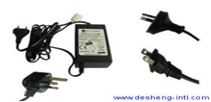
Intelligent Three Stage Charger |
|
|
Input: 100~240V, with USA, EURO, Australian, UK plug sockets are available. |
|
|
|
|
|
|
|
|
|
|
|
|
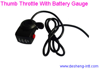
Twist/ Thumb Throttle With Battery Gauge |
 |
 |
Brake handle with electric switch / Padal sensor |
|
|
Battery Rack/Left Soft Plastic Handle |
 |
|
|
|
| How does this type of motor work? |
| MOTOR: |
The motor has three phases, or power supply wires (think of this as a 3-cyclinder automobile engine.) Each of these phases
fires in succession with the others, determined by the "Central Brain", or what is called the "PWM (pulse width modulation)
Controller." Inside the motor on the outer perimeter there are many "rare earth magnets". Closer to the center of the motor
are the wire coils, also wired in three phases. As a pulse of electricity is sent to the motor from the controller the coils create
a strong magnetic field, which repulses them from the magnets and causes the motor to advance (rotate) away from the
magnets.
The controller then sends another pulse of electricity and the next phase fires, rotating the motor even further. It's helpful
to think of our automobile engine example: 3 cyclinders - each firing one after the other.
There are three power (phase) wires going into the hub motor, and five Hall Effects Sensor wires coming out of the hub
motor. The Hall Effects wires are used only to help the motor start from a dead stop. If you have a "Pedal First"
controller (this controller requires that the bike be moving 3-5 mph before the motor will kick in), the Hall Effects Sensor
wires are not needed. |
| WORD OF CAUTION: |
the Hall Effect Sensor wires are thin, delicate wires that can be broken. The most common reason these wires get broken is
because the nuts, which secure the hub motor/wheel on the front forks are not sufficiently tightened. If the nuts are loose,
there is a possibility that the motor will spin within the forks, wrapping the cable into a ball, and severing the tiny Hall
Effects Sensor wires. In many cases, you cannot visually see that the Hall Effects Sensor wires are broken. When the
Hall Effects Wires are severed, the motor will not fire properly, i.e., the motor will vibrate or "chatter", in much the
same way that an automobile engine will run badly when one of it's cyclinders is not firing. Many people mistake the
"chattering" for a bad wheel-center bearing, when it is really severed Hall Effects Sensor wires. |
| CONTROLLER: |
How does the controller determine the speed at which the motor rotates?
The pulses of electricity sent to the hub motor are determined by the throttle, which is mounted on the handlebars of your
bicycle. The throttle is actually just a magnet passing by a "Hall Effects Sensor." Power is supplied to the throttle from
the battery. The throttle then rations a small amount of power: from 0 to 5 Volts, which it sends to the controller.
The amount of voltage sent to the controller is determined by how much the throttle is twisted. As the throttle is twisted,
"Hall Effects Sensors" read the amount of voltage, and send this amount of voltage to the controller. 5 volts means the
controller does nothing: sends no pulses to the hub motor, 0 volts means the controller sends electrical pulses to the
hub motor as fast as it can. |
| BATTERIES: |
The battery pack is the power supplier for your kit. You must look after it carefully.The batteries need to be recharged
immediately after EVERY use. They hate to be left in a discharged state, even if they are only slightly discharged. I repeat,
THEY HATE TO BE LEFT IN A DISCHARGED STATE! So, if you forget to recharge your batteries, leaving them
drained for even one day, you WILL damage them, and they will soon begin to give you poor performance. |
 |
 |
 |
| |
|
|
|
|
|
|